Sunday 30 October 2016

Input And Output


INPUT and OUTPUT

Difference between Input and Output Devices
Input and output devices performs two types of operations in a computer system. Input is any data that we send to a computer for processing. That can be an image from a Digital Camera, or some letters types via keyboard in a word document. Output is the result of the data we can see through some output device like a picture displayed by the Monitor, a word documented printed by a printer etc.

Input Devices

An input device feeds data to the computer system for processing.
Here is a list of input devices of a Computer System. We are going to discuss the most commonly used input devices in this article.

Complete list of Input Devices

  • Keyboard
  • Mouse
  • Scanner
  • Digital Camera , Camcorder
  • Gamepad, Joystick, Steering wheel.
  • Mic
  • Barcode Reader
  • Pen / Stylus
  • Touch Screen
  • Webcam
  • Biometrics (Thumb impression / Face detection)
Keyboard
Keyboard is the most common input device of a Computer System. The keyboard resembles a typewriter. Modern Keyboards have more than just the letter and numeric keys. They have multimedia keys for volume control, Play / Pause videos etc. Every single key on a keyboard is assigned a binary numbers to it which transmits that binarypattern to the computer.
Now, have you ever wondered why the keys on a keyboard are not in alphabetic order? The keys are laid out in the QWERTY order so that those key that are often struck in succession were not next to each other.  Therefore, the QWERTY layout is intended for slow typists. While for speed typing there is another keyboard available with "Dvorak" layout.
Same is the case with the numeric keys layout. If you have noticed, the layout of a Phone is different from that of a numeric keys on a Keyboard. It's because earlier phones cannot handle fast dialers. However, the layout of numeric keys on a keyboard are designed for speed typing.
Mouse
Mouse is another commonly used input device of a computer system. The mouse is a pointing device that moves the cursor on the screen. You can place the cursor on icons and by clicking you can launch a program. A typical Mouse has two buttons, the left and right clicking buttons and a wheel in the center for scrollingA user can perform many operations through a Mouse, like selecting or arranging different program icons on the desktop. Copy / Paste text in a word document, scroll webpages, and of course a mouse can come in handy while playing computer games.
There are two types of Mouse, one type has a rubber-covered ball at the bottom. As the mouse is slid on a surface, the ball rolls, resulting in movement of the cursor on the screen. This is the traditional type of mouse which is getting obsolete these days and this type of Mouse does not performs well on some surfaces. The other type is an Optical Mouse, which is popular these days. The optical Mouse tracks the Mouse position using the optical sensor. The optical mouse can perform well as compared to the traditional mouse.
 Scanner
Scanner is the third important input device of a computer system. A scanner converts printed documents in to images. Some types of scanners scan documents and produce the results in black & white images. The scanner operates in the same manner as a Photocopier. A colored scanner works somewhat in a complicated manner as compared to a simple scanner.
Digital Camera
Digital Cameras are used to capture images. Those images are then transferred to a computer when the Camera is connected to the computer. Mostly the Digital Camera images are in JPEG format.
Gamepad
A computer can serve many purposes. Besides work, a user can also play games on a Computer. You can use a keyboard and mouse for gaming but a specialized Hardware device, i-e a Gamepad can also be used. A gamepad is used for controlling games, with few buttons that controls the movements of character in a Computer Game.

Output Devices

Output devices displays the processed form of data to the end user.
Common Output devices include;
  • Monitor
  • Printer
  • Speaker
Monitor
Monitor is the most important output device of a computer system. The monitor is the display screen of a computer. Cathode Rays Tube (CRT) and Liquid Crystal Display (LCD) are the two types of Monitors.
                                                                
The CRT monitor looks like a television. At one end of CRT Monitor there is a device that produce electrons and bombard it towards the other end where the screen is located, resulting in the screen glowing because of a substance on the screen. The CRT Monitors are expensive and occupies more space as compared to LCD Monitors.
LCD stands for Liquid Crystal Display. It has the properties of both liquid and solid, that’s why it has a sharp and better picture quality than CRT Monitors. LCD monitors are relatively expensive then CRT monitors. Basically, the LCD monitors were designed for laptops. Nowadays they are getting popular because of its slim size and flat screen.
Printers
A Printer takes print commands from a computer and print out text / images on a paper. Different types of printers are available for various purposes. A printer for office use must be heavy duty and fast while for photographs it must produce high quality prints. Dot-Matrix, Ink-Jet, Laser-Jet are the different types of printers. Print quality of Laser-Jet printer is excellent as compared to Ink-Jet or other types of printers, but they are relatively more expensive than the others. Most laser printers produce black & whiter prints while some can produce color prints as well. The color laser printers are way too expensive then black & white laser printers.
                                                       
Speakers
Speaker is an important part of a computer system. Some systems have a built-in speaker, though they are small in size. Speaker is an essential part of a computer because they can notify about various system notifications through various sounds. Big speakers, woofers & sub-woofers are used for enhance sound quality or creating a mini home theater.

Arithmetics for Computers


BY MOHAMAD IZZAT FARHAM BIN ZAHARI

DO31610168

6 : INTRODUCTION TO THE COMPUTER LANGUAGE


6.1.1 FORTRAN

The first computer language for electronic devices was short code


 The first of the major languages appeared in the form of FORTRAN
-FORTRAN stands for Formula Translation system
-FORTRAN language was designed at IBM, for scientific computing
-The language used for programs that benchmark and rank’s the world fastest super   computers is FORTRAN


6.1.2 COBOL  (COMMON BUSINESS ORIENTED LANGUAGE)


6.1.3 ALGOL ( ALGORITHMIC LANGUAGE)


ALGOL is a high level language designed specially for programming Scientific Computations

  - Develope by an international group in Europe consist of 7 countries in the late of 1950's
  - Very similar to FORTRAN


6.1.4 C++


C++ language was known as Object Oriented Programming or OOP.

C++ is most after used in simulations, such as games.

C++ is sometimes called a hybrid language.

One of the preferred programming languages to develop professional applications is C++


6.1.5 JAVA


· Java is a programming language developed by James Gosling.

· Java language was developed to facilitate communication with the interactive T.V.


BY MOHAMAD IZZAT FARHAM BIN ZAHARI

DO31610168

10 : PARALLEL PROCESSING


A mode of computer operation in which a process is split into parts that execute simultaneously on different processors attached to the same computer.


 The ability of the brain to do many things (aka, processes) at once. For example, when a person sees an object, they don't see just one thing, but rather many different aspects that together help the person identify the object as a whole. For example, you may see the colors red, black, and silver. These colors alone may not mean too much, but if you also see shapes such as rectangles, circles, and curved shapes, your brain may perceive all the elements simultaneously, put them together and identify it as a car. Note that motion and depth of the object can also be perceived. These cues processed in the brain tell the person that the red car is headed straight at them so they jump out of the way. Without parallel processing, the brain would have to process each aspect of the car separately in progression. By the time the person identified the car, it would be too late.

Saturday 29 October 2016

DIGITAL LOGIC SIMULATOR
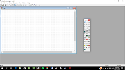
Multimedia logic is a drag and drop logic design software. You can draw your logic design on the white canvas and then we can stimulate the circuit.

To draw the circuit you need to choose which component needed to built the circuit. The mouse pointer indicates as selector. Use this to select and move icon. To delete an icon , use selector and select the icon. Once an icon is selected, press the delete button on your keyboard.

STEP 1

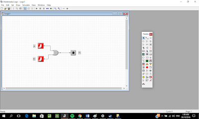
Find the logic AND in the pallete, click the AND gate and place it on the canvas


STEP 2

Find the switch and click the switch, place the switch on the canvas near the input of the gate.the switch would look like the figure below

STEP 3
Find the LED icon and place on the output side of the gate.

STEP 4
To connect each component, use wire icon to connect each dot to the respective gate. Click at one end and drag to the other end.

STEP 5

Label the input and output accordingly. Find icon “A” and click next to the input. To edit the text, click the mouse pointer on the palette and double click the label text to open text properties. Type the input label on text box, then click OK.

STEP 6
Stimulate the logic by clicking the stimulate menu, choose run. Or you can just click the play button to run the stimulation.
Test the AND truth table by clicking the switch to see whether LED will light on. LED will light on if the condition is met. In this logic, only when all switches is set to 1 then the LED will light red.

To stop the simulation, press stop button.
The circuit can be save into .lgi file or printed by sing the file menu.


Friday 28 October 2016

INTRODUCTION OF DIGITAL LOGIC
Digital logic is the fundamental concept underpinning all modern computer systems. Put simply, it’s the system of rules that allow us to make extremely complicated decisions based on relatively simple “yes/no” questions.

·      COMBINATIONAL LOGIC

1)       A logic block contains no memory and computes the output given the current inputs.
2)       Can be defined in three ways:
a)       Truth Table – the truth table shows many possible combination of input values, in tabular from between the input values and the result of a specific Boolean operator or combinations on the input variables.

b)       Graphical Symbols – the layout of connected gates that represent the logic circuit
a)       Boolean Equation – Boolean function that consist possible combination of inputs that produce an output signal
(1)     Examples:
·      BOOLEAN QUATION FORM
A Boolean algebra is the combination of variables and operators. Typically it has one or more inputs and produces an output in the range of 0 – 1. The complement of a variable is shown by a bar over the letter.
All Boolean equation can be represented in two forms:
1)   Sum-of-product (SOP)
a)   Combination of input values that produces 1s is convert into equivalent variables, AND-ed together then OR-ed together with others combination variables with the same output.
SOP is easier to derived from truth table.
1)   Product-of-sum (POS)

a)   Input combination that produces 0s in sum terms ( OR-ed variables) are AND-ed together.
b)   Convert input that produces 0s into equivalent variables, OR-ed variables, then AND-ed with other OR-ed variables.
·     SIMPLIFICATION OF BOOLEAN EQUATION

There are two ways to simplify Boolean equation, Laws of Boolean Algebra and Karnaugh Map.
·        Laws of Boolean Algebra – rules to simplify Boolean expression
·        Karnaugh Map – A grid-like representation of a truth table

·      Laws of Boolean Algebra

Boolean expressions can be simplified or manipulated. Table below shows the basic rules of Boolean Algebra to help manipulating logic equations.
·      Karnaugh Map


The Karnaugh map provides a simple and straight forward method of minimizing Boolean expressions. The only limitation is that it will be ineffective for more than 4 inputs.

The Karnaugh map can also be describe as a grid like representation of a truth table. The rows and columns corresponds to the possible values of the function inputs.

A product term that includes all of the variables once, either complimented or not complemented is called a minterm. For example, if there are two input values A and B, there are four minterms A’B’, A’B , AB’, AB, which represent all of the possible input combinations for the function.


EXAMPLE OF MINTERMS


Karnaugh map can be applied to expressions of more than two variables. We simply extend Karnaugh map for two variables to three variables as indicated in the above figure.

·      GROUPING 1’S IN KARNAUGH MAP
a)     The group can only contain 1s.
b)     Only 1s adjacent cells can be grouped; diagonal grouping is not allowed.
c)     The number of 1s in a group must be a power of 2, means a group can contain 2,4,8,16 of 1s.
d)     The group must be as large as possible while still following all rules.
e)     All 1s must belong to a group, even if it is a group of one.
f)       Overlapping groups are not allowed
g)     Use the fewest number of groups possible


·      SIMPLIFIED EQUATION TO LOGIC CIRCUIT


                                I.            A SYMBIOSIS PROCESS: for every Boolean expression there is a logic circuit, and for every logic circuit there is a Boolean expression.in other words, we can derive the other if we have one of them.
                             II.            Simplifien L2 is represented into logic circuit
                           III.            From the L2 equation the SOP equation is the input for L2 (output). There are 3 inputs s1,s2, and s3 where 2 input will be AND-ed and OR-ed with 2 AND gates.
                          IV.            If any other 2 AND gate variables such as AB + A’C,we still use 3 inputs,A,B and C as A’ can be represented using an inverted A.
                             V.            Figure below shows the logic circuit that represent L2 function

·      UNIVERSAL GATES
Gates that can be used to implement any gates ;ike AND, OR and NOTor any combination  of these basic gates are called universal gates. NAND and NOR are such examples.
                 I.            NAND GATE
A NAND gate is a logic gate which produce an output that false only if all of its inputs are true. Figure below shows the truth tableand graphical symbol of NAND gate.

                 I.            NOR GATE

A NOR gate is a logic gate which produces a high output (1) results if both the inputs to the gate are LOW(0); a LOW output (0) results if are both inputs is HIGH (1). Figure below shows the truth table and graphical symbol for NOR gate.